I have already provided many posts detailing the cabinet and playfield progress (with many more to come), and now it is time to talk about something different, the electronics of the pinball machine.
Anyone who has seen the inner workings of pinball machines is familiar with the large, complicated circuit boards hidden inside. These electronic boards are custom designed for pinball machines - often specific to a single game design. Hundreds of color coded wires run from these boards to other boards, the playfield, and other areas of the cabinet. It's an electronic nightmare.
 |
| Found on the web, this ActionPinball.com image shows many of the common circuit boards hiding in a pinball backbox. |
When I first started the project, I briefly considered using these original pinball circuit boards - after all, if it already works why re-invent the wheel.
But using 30 year old circuit boards, possibly designed for an incompatible game and running hard coded firmware, just didn't align with any of my goals. Nothing modern about that approach. Rather, I wanted to use off the shelf, generic circuitry where possible. Besides, these pinball specific circuit boards are expensive.
I also looked at programmable microcontrollers like Arduino and Parallax. +Ben Heck had chosen the programmable microcontroller path for his pinball machines, and I knew it was cost effective and functional, but I found this approach was too limited for some of my goals. Sure, these devices were powerful, and could easily control lights, solenoids, switches and audio, but I wanted video too.
More importantly, I wanted a solution that could adapt to any pinball machine without writing new code.
From this point forward I will begin to show you what makes the Modern Firepower Pinball Machine so special, and unique in all the world of pinball.
At a basic level, the function of pinball electronics can be summarized as follows:
- Receive input signals from switches and buttons
- Switch outputs on and off, like lights, solenoids and motors
- Run game routines to process inputs, outputs, score the game and play audio
 |
| Version 1 of the LED-Wiz output controller. I have version 2 which adds the ability to assign different voltages to 4 banks. |
The LED-Wiz is a 32-port USB lighting and output controller, and it was advertised as capable of controlling not just the game lights but also high powered devices like the solenoids as long as I used switching transistors between the LED-Wiz and any high powered devices.
 |
| The U-HID universal interface board. |
The U-HID is a USB keyboard/mouse/gamepad controller that can read all the various switch and button inputs. It has 50 separate inputs. It also has the capability to control LED's, though I will not use the U-HID in this fashion.
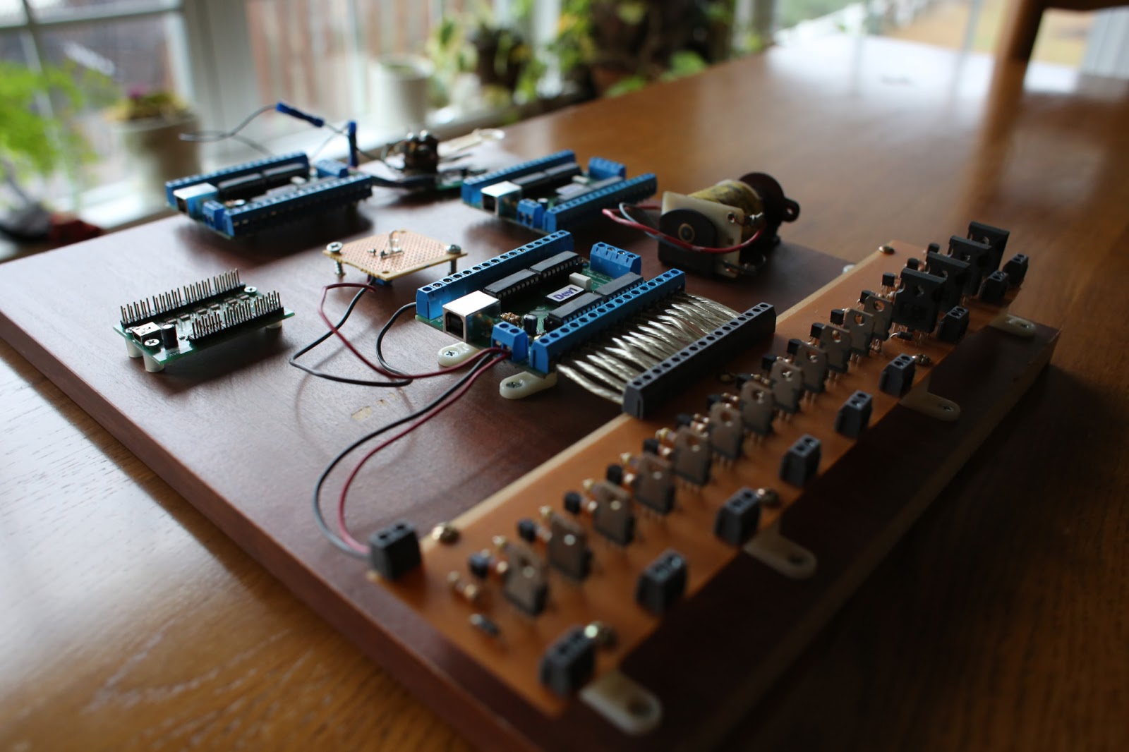 |
| My original prototype board, with 3 LED-Wiz's, a U-HID, a U-HID G, my Power Driver board. Also mounted to the board are a test solenoid, a pop bumper switch, and a regular LED (I did not have any pinball LED bulbs at this time). |
The key takeaway for both of these devices is that they are USB devices, designed to connect to any normal PC. They are also compatible with multiple OS's, including Windows and Linux.
A LED-Wiz is only capable of controlling 32 outputs, but multiple LED-Wiz's can be connected to the same computer (up to 16 boards for a total of 512 outputs!). The Modern Firepower playfield has 13 solenoids, 51 playfield lights, and about 18 more general illumination lights, for a total 80 outputs I needed to control. Controlling 80 outputs required 3 LED-Wiz boards, but also leaves 18 outputs unused, so it could easily handle a more complicated playfield that has more solenoids or lights.
As a side note, while wiring all of the GI lights together as a single output would drop the total number of controlled outputs to 63, I would still need 3 LED-Wiz boards. Due to the LED-Wiz design, the 32 outputs on the board are grouped into four groups of 8 outputs (called banks) that must share the same voltage, and I will have 3 voltages to manage. The 13 solenoids share a voltage, so that will take 2 banks, using 16 outputs. 50 light outputs will share a voltage, so that will take 7 banks, using up 56 outputs. And the 'FIRE' and 'POWER' flasher lamps will share a voltage, so that will take 1 bank, using 8 outputs. Totaled up, that requires 80 outputs, so 3 LED-Wiz boards are the minimum for this design, even though 17 of the 80 required outputs would go unused.
 |
| Each LED-Wiz is factory assigned a Device # (this one is Dev1) allowing multiple boards to be used on the same PC. Here I have connected 16 of the 32 outputs to my Power Driver prototype board, leaving the other 16 available for lighting. |
The U-HID can run in different modes, including keyboard, mouse and gamepad. It seemed that only gamepad mode allowed for simultaneous button presses, unlike the keyboard mode, and was most suited to pinball machine use. Even though the U-HID has 50 inputs, but only 32 are addressable as gamepad buttons (this is a Windows limitation for all gamepads), so the remaining 18 would be treated as keyboard buttons. I will use those 18 inputs in switch locations unlikely to see concurrent key presses, though in my code I have written special logic to minimize any issue this would cause.
Counting up all the switches on the Modern Firepower playfield, there are 10 stand up targets, 8 stand up switches, 9 rollover switches, 2 star rollover switches, 4 pop bumper switches, 2 slingshot switches, 3 eject hole switches, 7 ball trough optical switches, and 1 spinner switch, for a total of 46 inputs from the playfield alone. That leaves only 4 more inputs. I could have squeezed the two flipper buttons, a credit button and a tile switch in there, but I wanted more flexibility. I also didn't like the idea of playfield switches and cabinet switches being connected to the same device.
 |
| The U-HID is tiny but still has 50 separate inputs. In gamepad mode I can read the state of 32 switches simultaneously. |
U-HID also has a smaller version named the U-HID G, which offers an additional 8 inputs that are perfect for the flipper buttons, credit buttons, and coin door buttons, and it also has a built in 3-axis accelerometer. This separate board would be installed to the cabinet, instead of the playfield, allowing wiring isolation, and the accelerometer feature could also be used as a programmable tilt sensor.
 |
| Making the U-HID look large, the nano sized U-HID G offers 8 inputs plus a built in 3-axis G sensor. |
I have recently read some comments that calibrating the 3-axis accelerometer is very problematic, and my brief testing with the device leads me to believe there's a real issue here, so I've also picked up an original pinball tilt switch which I can wire up to one of the 8 inputs on the U-HID G if the G sensor doesn't work out.
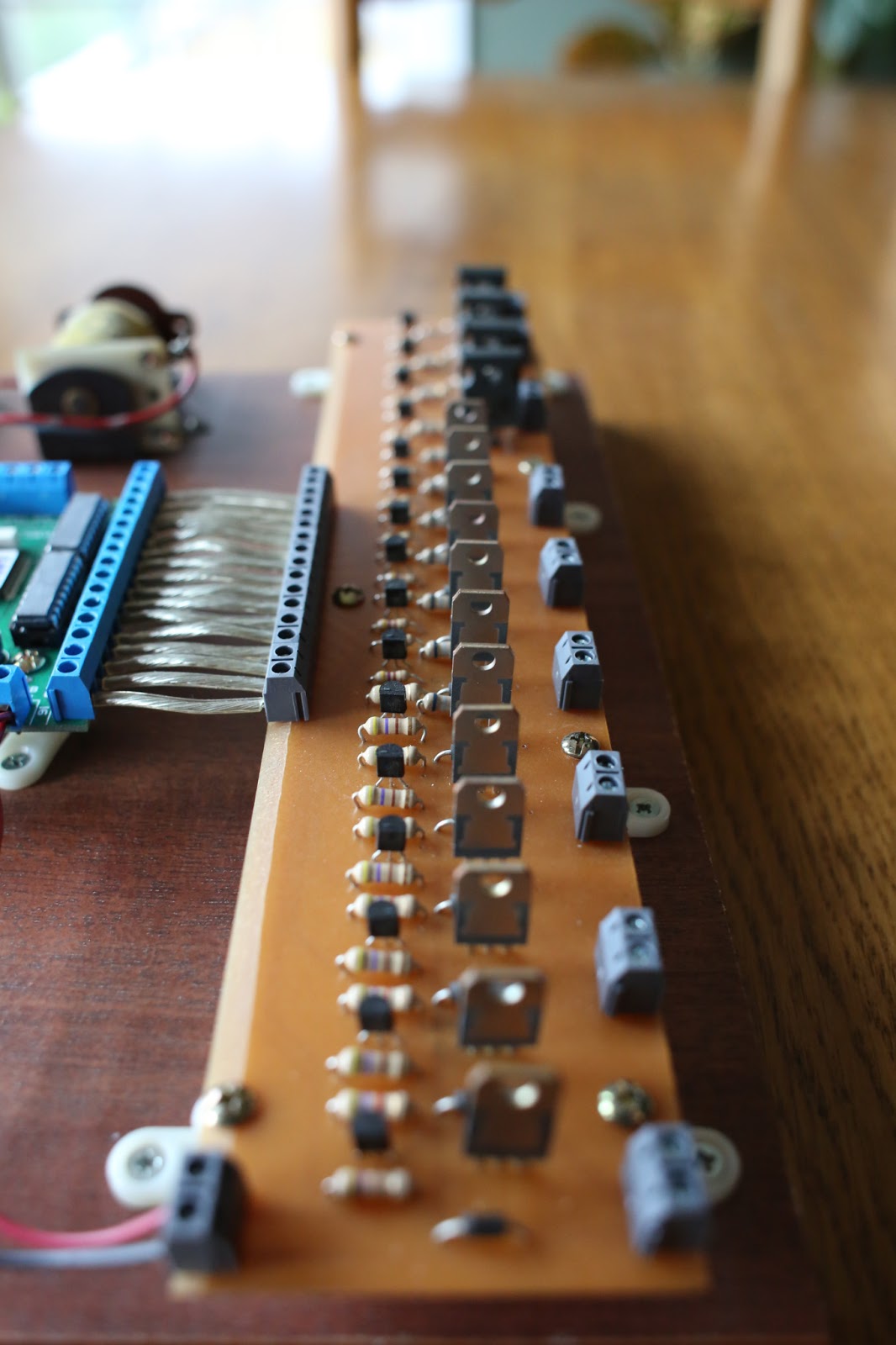 |
| My homegrown Power Driver Board has 12 'Low Powered' circuits. I found that these died after only a few minutes of testing. I'm not sure what pinball devices are suitable for 'Low Powered' circuits, but I won't be using them. |
While the LED-Wiz is capable of switching outputs, it can only directly handle low powered outputs like LED lights. To handle high powered solenoids (I'll be running mine at a deadly 50 volts), I had to design a Power Driver circuit board. Basically this is nothing more than low powered transistors switching high power transistors. My first prototype was a success, but I am in the process of refining the design for more reliability and user safety. I hope to finish the new version in a few weeks.
 |
| My Power Driver board also has 4 'High Power' circuits that integrate larger TIP 36C transistors (top of image). These didn't blow up in testing, so I will make all of my circuits as 'High Power' circuits. |
For the PC, I wanted something small and affordable, but robust enough to live in a pinball machine. Originally I planned to use an old clunker of a PC I have laying around, but decided I wanted something a little more impressive to show off the project. For a while I was thinking of a Mac Mini running Windows, but kept balking at the high price and didn't want to confuse people into thinking my pinball software ran on Macs.
Finally I found the Zotac brand of small PC's, and picked up a ZBOX nano PC. Barely larger than a CD, it comes with a VESA mount so I can install the PC in the backbox attached to the TV (I mentioned in an earlier post that I'm using a TV for the backbox artwork and scoring). Even with 8GB of RAM, a 120GB SSD HD, and Windows 7, the price is less than a Mac Mini.
For those curious, the specific model I purchased is the Zotac ZBOX nano 'ZBOXNANO-AD12-U' which has a dual core AMD APU (Accelerated Processing Unit) that combines the CPU and GPU onto a single chip. I did not purchase the 'Plus" version of the AD12, which adds a limited 2GB of RAM and a mechanical hard drive - I thought a vibrating pinball cabinet might not be a good match to a spinning hard drive.
 |
| New in the box, a Zotac ZBOX nano PC with AMD Processor, plus an SSD Hard Drive, 8GB of memory, and Windows 7. |
While I'm paying a premium for form factor, I believe that almost any $200-$300 PC has enough horsepower to run my pinball software. My original testing was successfully performed on what is now an 8-year old laptop running Windows XP, so that should give you an idea of the software's efficiency.
 |
| I simply opened up the ZBOX and installed the memory and HD to complete the PC build. Only took a few minutes. |
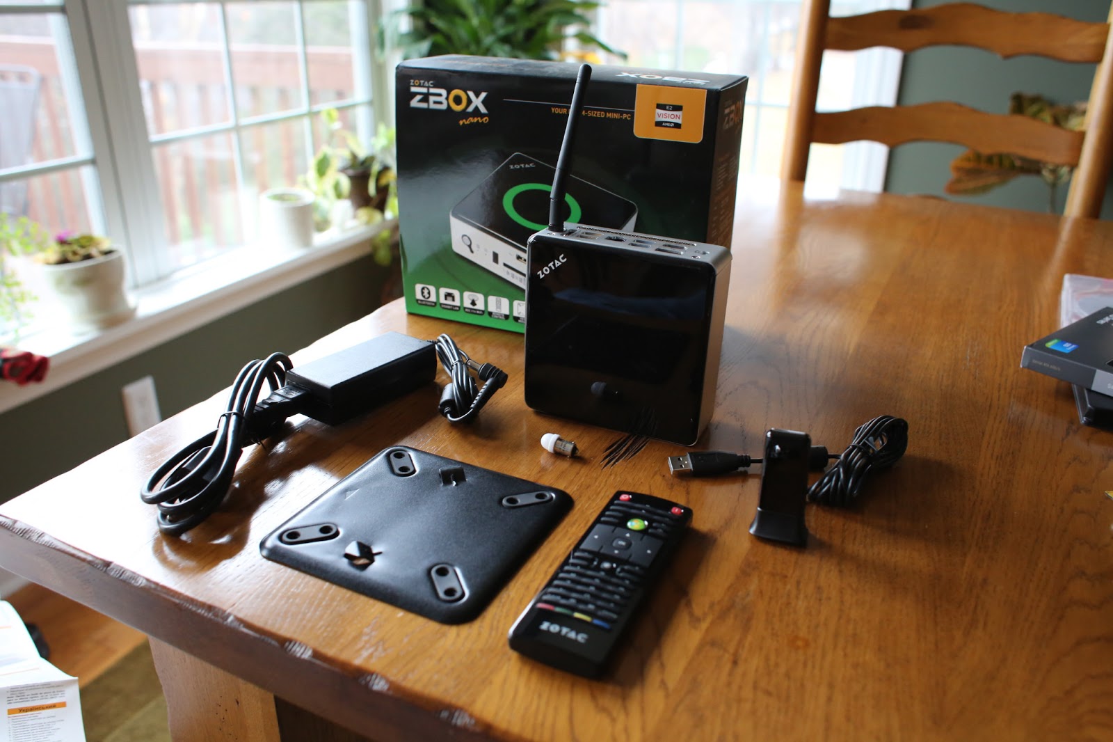 |
| The ZBOX comes with (left to right) a power supply, VESA mount, remote control, and IR receiver. The ZBOX also has built in WiFi, notice the antenna on top. I included the small white pinball LED in the middle to give a sense of scale. |
 |
| For size comparison, you can see that the ZBOX nano is barely larger than a CD. It is too small to actually have a CD drive. |
So these components became the basis for the electronics for The Modern Firepower Pinball Project - a Windows PC connected via USB cables to 3 LED-Wiz boards, a U-HID board, a U-HID G board, and a homegrown Power Driver board.
With the exception of the Power Driver board, these electronic devices are all off the shelf components that are not even Pinball specific. Additionally, the USB boards are small devices that I plan to install directly to the playfield, which I believe will dramatically reduce wiring complexity.
Add in my Power Driver board (which technically could be used to switch any high powered output, not just pinball solenoids) and my pinball software, and what you have is a diy bundle that could be used to control any pinball machine, homegrown or retrofit.
If there is enough demand, I will consider producing these bundles for DIY pinball enthusiasts.
Over the coming weeks, I will show how these components work together and with the software - combined with this hardware, the software is truly groundbreaking. The best is yet to come!
No comments:
Post a Comment