This update should have been posted last October, but I got sidetracked. Better late than never, eh?
My PCB order from JLCPCB arrived on October 1st, and luckily all boards looked perfect. For this order, I had the PCB's panelized, so I could assemble them on my Pick'n'Place machine in batches of six.
 |
| The Chameleon Power Driver v5 PCB's waiting for assembly |
I made a pretty cool video showing the PCB assembly and validation process - it's a surprising amount of work: Chameleon Power Driver v5 Assembly
At the end of the video you can see a brief glimpse of my new testing jig. I custom designed and 3D printed this jig to test each power driver. There are spring loaded POGO pins inside that make contact with various test points on the PCB.
Click through for the rest of the details.
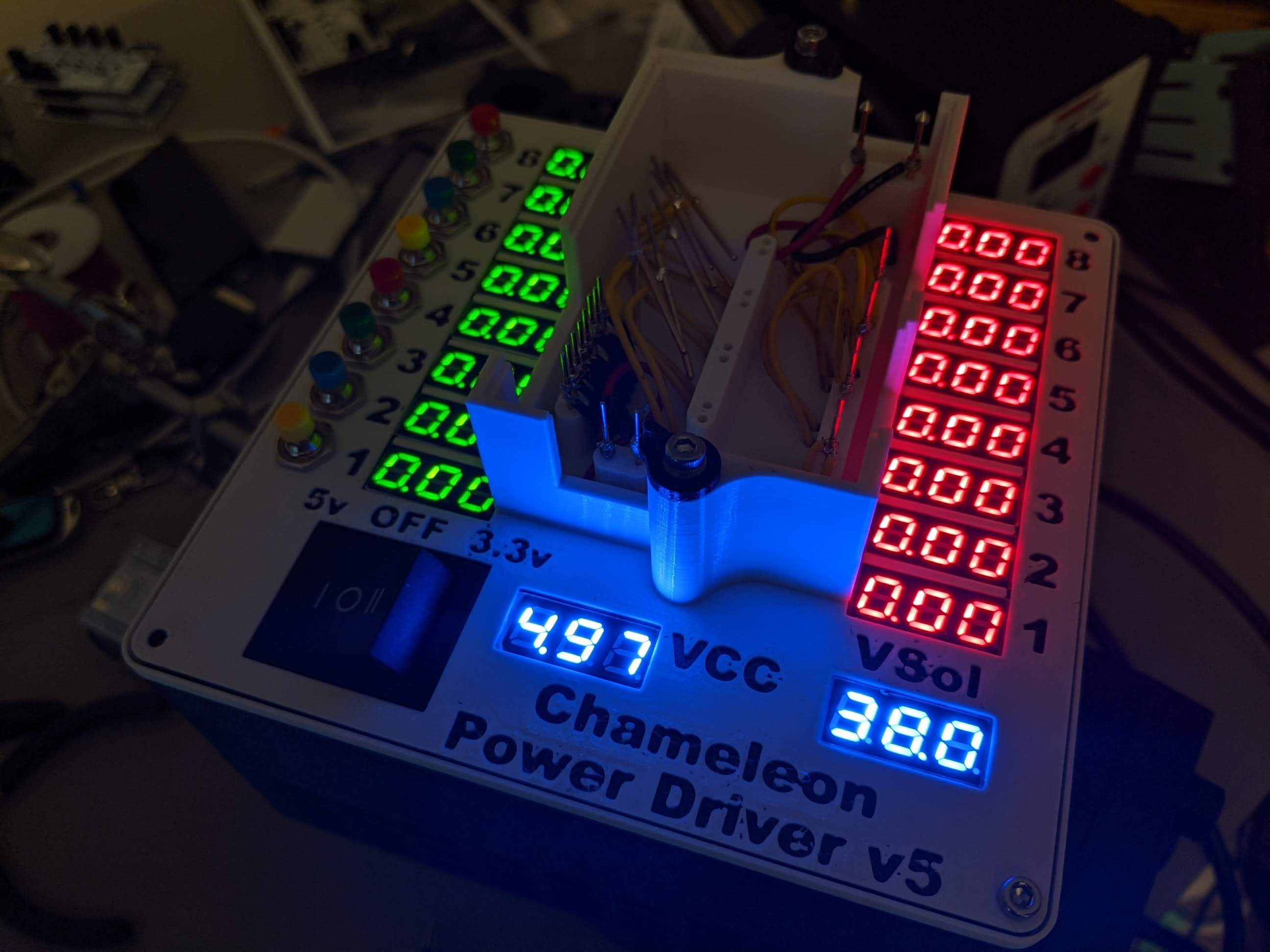 |
| My custom 3D printed test jig lets me easily validate each power driver works correctly |
It has two power supplies inside, both 5v and 3.3 volt, and I test with both to ensure the power driver accepts both levels as control signals. I primarily designed the power driver to work with 5v signaling, but on paper the NPN transistors are right on the edge of supporting 3.3v for Arduino/Pi compatibility. I figured it might work on a few boards, and I was surprised that 3.3v signaling worked perfectly on all six test boards. I actually test with <3.2v to validate compliance with 3.3v signaling.
I connect an external benchtop power supply to test the solenoid level power handling. The power driver does have a limited range of acceptable voltages, too low or too high and the MOSTFET's won't switch correctly. I tested all 6 boards with a range from 12v lows to 60v highs, which is my designed operating range, and again all boards worked perfectly.
The test jig isn't perfect. The digital voltmeters I purchased have a low resistance, so low in fact that they alter one of the power driver circuits, changing the measured voltage and switching behavior. I ended up having to disconnect that part of the test jig. And while I did include more test points on the v5 power driver PCB design, I should have added even more and spaced them further apart, as it would have made this test jig easier to build and use. Next time I will design the test jig along with the PCB.
 |
| One of the new Chameleon Power Driver v5 boards installed on The Black Knight Rises |
No comments:
Post a Comment