I can't believe it's been almost 4 years since the last project update here. I'm sure everyone has assumed The Black Knight Rises is DOA.
I'm happy to say that not only is it not dead, but for the first time in a while, the project is making great progress!
Yeah, this is a long post. It's hard to wrap up 4 years in a couple paragraphs.
What Happened?
In the summer of 2017 I needed a break from working on the The Black Knight Rises. Building a complete pinball machine from scratch, designing and assembling my own electronics, writing firmware, programming the pinball software, and troubleshooting issues coming from every direction - it was just all too much.
Click through below to follow along on the journey and see the great new developments!
For a distraction I wrote a home-theater software front-end for the My Movies movie collection management program. I thought it would take a couple weeks (and technically it did), but then I got the bright idea (sarcasm) to try selling it online. I had no idea what I was in for - years of user support, bug fixes, and new program features. The end result is truly awesome, check out Chameleon MediaCenter (CMC) if you're curious to know more.
 |
| Chameleon MediaCenter (CMC) is a modern front-end for movie buffs who like to own their stuff. |
After over three years of non-stop focus, CMC is finally to a point where for the most part it just works, is mostly complete, and requires little in the way of day-to-day support anymore.
I'm not saying I didn't work on Chameleon Pinball for all those years - on occasion I squeezed in some work, but for the most part I kept hitting roadblocks and progress was minimal.
One side effect of my detour is that CMC challenged me far beyond my programming skills at the time. For four years, I've had to constantly learn new techniques and improve my programming abilities. I'm a significantly better programmer today than when I first wrote Pinball Chameleon Engine. Back then, I struggled to put together working functions, and wasted time trying to solve problems that didn't actually exist. I'm excited to see how I can apply my newfound abilities to my older pinball code.
The Chameleon IO Controller
From the Black Knight Rises project, you may already know that I designed and assembled my own custom pinball controller. This is a USB peripheral that you plug into a PC, letting the PC control 112 outputs plus provides 56 HID joystick buttons, all in a small 3.5" x 4.25" board. To get it this small, I had to use modern surface mount components (SMD) for system chips, resistors, capacitors, drivers, and other various parts. The smallest components are 0402 sized, about the size of a flea, and in the beginning I was using tweezers and a magnifying glass to assemble the boards. And these weren't even the hardest parts to place, as some of the integrated circuits have even smaller pads and require accurate placement to within a fraction of a millimeter. My miniaturization goals here were a bit too ambitious, it seems.
 |
| All roads may lead to Rome, but all these wires lead to the Chameleon IO Controller. |
The very first board I assembled by hand actually worked (a fluke, as it turns out) - well, kinda worked. It had a fatal design flaw: I had shared the LED output power with the system chips, and after turning on more than a dozen LED's the voltage would sag enough to cause the controller chips to reboot - DOH!
At first I tried to mitigate this will better power supplies, but that wasn't good enough. Eventually I did a v2 redesign, and created two separate voltage planes, one for powering the 4 integrated circuits and another for LED output. I also spent the big bucks and bought a professional solder paste stencil. That was back in 2016. Problem solved, right?
Well, until a few weeks ago, I really didn't know...
Over the years I tried several times to assemble a working Chameleon IO Controller v2, and none worked, not a single one, and I didn't know why. Either I made a mistake in the power redesign, or I wasn't successfully assembling the boards.
I bought a manual Pick and Place machine - which is a small vacuum powered nozzle on a manually operated sled. The "ezPick" was a definite improvement over using tweezers, but wasn't quite up to the job of accurate placement for the smallest pitch components, since the weak component is still the shaky human hand controlling placement.
 |
| The "ezPick" manual Pick and Place machine. "Machine" seems like a misnomer here... |
I tried several times in 2017 to get a working controller board to power The Black Knight Rises for the Southern-Fried Gaming Expo, somehow all failed to even power on.
I was throwing money away hand over fist, as every defective board cost me well over $100 in parts, plus a full day of my time doing assembly. Several thousand dollars spent, I felt defeated and broke, and I put the project aside for a while.
In the back of my mind, I kept thinking my v2 design was flawed, and that it was beyond my ability to even understand what I did wrong. It bothered me that my first v1 board worked the first time I assembled it. How was I failing consistently with this v2 design if my design itself wasn't the problem, surely it wasn't just luck that very first time. I definitely didn't feel like spending more money to learn the answer.
The Pick and Place Machine
After attending the Southern-Fried Gaming Expo in the summer of 2018, and having an awesome chat with Jimmy Lipham (look him up if you don't know his impressive resume in the pinball community), I was motivated enough to make another go at assembling the IO Controller v2.
First, I reviewed the v2 design for hours upon hours, until my brain hurt with exhaustion, and came to the conclusion that my split power plane design seemed okay. Logically, it should work. The unknown element for me was if USB controllers had some kind of safety logic to disable power unless certain conditions were met. This seemed unlikely, though it would sure explain why none of my v2 boards even powered up.
I had some design reviews with electrical engineers, none of whom could point to anything I did wrong, though they stopped short of saying my design was right. This was because I had taken a few liberties in my USB power implementation, skipping some special USB hub power control circuitry that I thought was unnecessary in my static design with a known power consumption.
While design issues remained a possibility, the case was strong that PCB assembly was the real issue.
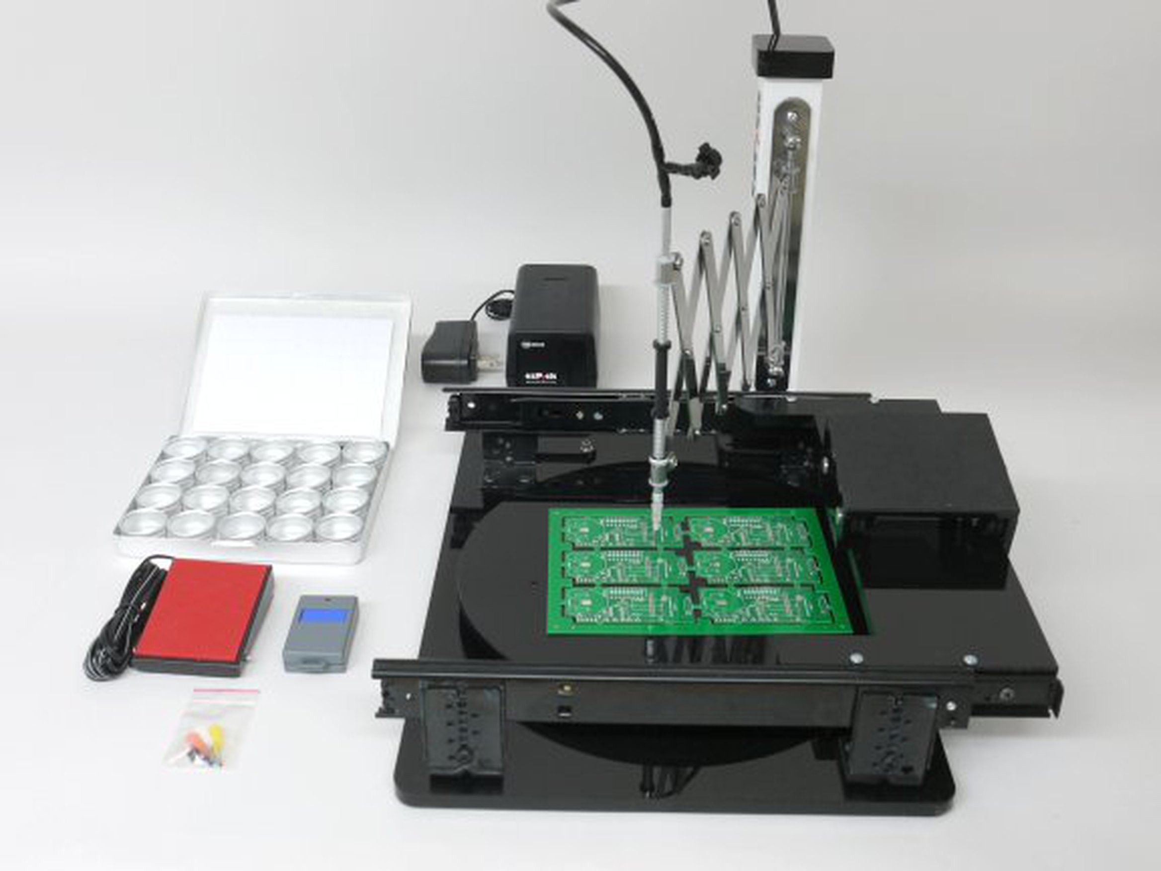
So I made a crazy decision and bought a robotic Pick and Place machine - the CharmHigh CHM-T36VA. It seemed pretty sweet, with over two dozen feeders for component tape reels, trays for picking up stand-alone integrate circuits, dual pick-up nozzles for faster board assembly, and a dual camera cameras to automatically identify and correct part orientation for accurate placement of tiny 0402 sized components. Surely this expensive machine would succeed where I had failed. It was a huge, expensive investment and a real gamble, considering how much money I had wasted up to this point.
| The Charmhigh CHM-T36VA. The VA stands for Vision Assist - it uses camera for accurate placement. |
Many weeks later I had the CHM-T36VA set up and started doing some testing. One limitation of the machine was that it could only pick up and place components that were under 5mm tall. But the Chameleon IO Controller has 32 components (mostly wire headers, but also some capacitors) over 5mm, 30 of those were 10mm tall. Unsatisfied, I spent many weeks modifying nozzles and 3D printing custom pick-up trays, and finally had a solution for picking up those 10mm tall parts!
Global Parts Shortages
With the machine ready to put through its paces, all I needed were the dozens of Chameleon IO Controller's components on tape reels for the machine to use. Little did I know that there was a global shortage of small SMD components, and I couldn't find most of what I needed. At the time, the projected part delays were 6+ months. I didn't want to place a piecemeal order, or get in a backorder queue, so I didn't place any orders at the time. The project was on hold again until January 2019 at the earliest.
When I checked again in January, the backlogs were still there, but were affecting different parts now. I was too busy supporting CMC at the time to worry much about it. The rest of 2019 was a blur, slipping by without the IO Controller getting much attention.
Then 2020 happened. My mind was on other issues, and the Chameleon IO Controller was the least of my concerns.
Finally 2021 arrived, and I decided to give it another go. It's frustrating that when you let a project sit for so long, you have to try to remember everything you learned and forgot a lifetime before. With great effort, I got the parts ordered after finding substitute components for several that were no longer available, and everything I needed arrived in March.
Prepping for Automated Assembly
Even though I now had all the parts, I was filled with dread about the next step - assembly. Over the past few years my mind has shifted back and forth on the root issue - one day I would think it was a flawed power circuit, and another it was simply an assembly issue. I think the dread I felt was the fear of proving my design was flawed, mainly because I couldn't see any flaws. As long as I didn't prove it was flawed, there was still a glimmer of hope that didn't make a huge mistake - ignorance is bliss. And if I discovered it was flawed, it was most likely the end of the project - too much time and money wasted to commit to spending more. Plus it would serve as proof I wasn't smart enough to master this build.
So I did other things instead.
A few months later, in June, I finally got beyond my fears and started playing with the Charmhigh CHM-T36VA again. I had to relearn how to use it, and configure it for the tape reels which I had never used before. Then followed tons of testing and tweaking system settings to get it to accurately pick up the components and place them correctly.
 |
| Testing placement of a 0402 capacitor. That tiny little flea is on there, placed perfectly. Do you see it? Once you find it, look left at E5 (right next to Switch Bank 5), and realize how small those pads are that even a 0402 flea sized component dwarfs them! |
Running a Pick and Place machine was a whole new skillset I had to develop. I wrongly assumed you simply loaded parts, loaded a pick and place list, and hit play. It was a ton of calibration and job programming, but finally I had 4 separate jobs using 6 different sized nozzles that was actually working. It had only taken 3 years to get to this point.
I'm sure there are some of you wondering why I didn't just get an assembly service provider to do all this for me. Good question. It sure would have trimmed a few years off my development time. But in all fairness, I had no idea my timeline would go off the rails so badly. Cost was my main factor, and I do enjoy these tasks. Why let someone else have all the fun? Yes, this is a mistake I make over and over and over again. Perhaps I'll never learn...
Solder Paste Stencil Misalignment
July rolled around, and I was finally ready to assemble my first board using actual solder paste - up to this point I had been using double-sided tape and re-using the same parts to minimize parts waste. With the tests looking good, it was time to get real.
 |
| Microscope image confirming alignment of stencil to pads. This entire area is the size of a tick, these pads (and the spaces between them) are smaller than fleas!!! Alignment is critical to success. |
In the process of applying solder paste, I discovered a new defect in my prior assembly process. In my attempt to make every step as accurate as possible, I am now using a microscopic camera to do alignment of the solder paste stencil on the PCB before squeegeeing the paste, to make sure it is placed accurately on the super tiny and closely spaced pads. You can see this in the screen grab above. Correct alignment is a critical step, since if you don't have paste on the pads, the reflow won't work correctly, and assembled board won't work.
 |
| Examining solder paste that has been squeegeed onto the PCB through a stencil |
The microscope was letting me see details I had missed before. After spending half an hour of tweaking to get the alignment perfect, I squeegeed on paste and then used the microscope to check my work and it was horrible - somehow the paste had shifted a fraction of a MM and was no longer on the smallest pads!
And in case you have experience with reflow soldering and want to shout out that the solder mask will fix this issue for you - not at these pitches. Some of my parts are so small, there is no solder mask between the pads - none! The pitch is simply too small for solder mask to be applied between the pads. The design rules for these part recommend skipping the solder mask and instead you must achieve perfect paste disposition and perfect part placement! I mentioned earlier that my miniaturization goals were a bit overzealous, didn't I?
 |
| Notice the solder paste (globs of tiny silver balls) between the pads, top-left. That's not gonna work. |
Paste misalignment, combined with my shaky hands trying to do manual part placement, is probably why I couldn't get any v2 boards to work. Another clue - this was my new professional stencil for the v2, and I had used a cheap stencil taped to the PCB for v1. The stencil paste misalignment was a new issue with v2. The pro stencil was in a metal frame, which prevented me from taping it onto the PCB. Instead, I was using a manual solder paste press, basically a metal jig that lowers the stencil onto the PCB and holds it in place.
 |
| My manual solder paste press - the long threaded rods at the back flex during swiping, causing misalignment. |
I finally realized that my manual solder paste press was flexing as I pulled the squeegee. It didn't matter how long I spent aligning the stencil, as soon as I swiped the squeegee it easily dragged the stencil out of place. This discovery was huge, and gave me hope that my design might work after all.
For a quick hack, I positioned the stencil a fraction out of place, and then squeegeed again. Somehow this actually worked, and I had paste in all the right places.
 |
| After mis-aligning the stencil before squeegeeing, the end result was near perfect solder paste on pads! Notice that these small pads have no solder mask (white) between them at all, they're too closely spaced to used solder mask between them. The width of each pad is only 0.20mm. |
Since then I've 3D printed some custom mini adjustable linear clamps that will allow me to hold the stencil in place during squeegeeing. Hopefully problem solved, but I haven't tested my solution as of yet.
 |
| Miniature adjustable linear clamps that I designed and 3D printed should prevent stencil shifting while swiping paste. |
Baking Challenges
After the Charmhigh pick and place machine did it's best (which really isn't all that great, but marginally good enough), I spent 30 minutes examining everything with the microscope, and manually nudged a few components that didn't end up perfectly where they needed to be. It was finally time for baking.
 |
| CHM-T36VA first completed assembly of the Chameleon IO Controller v2, ready for reflowing. |
For those that don't know, solder paste is a liquid solder that you bake in a reflow oven so that the tacky liquid flux carrier evaporates leaving behind microscopic metal solder balls, and the metal solder melts and joins your components together. These ovens can be expensive. Years ago I was really cheap and built my own reflow oven using a toaster over and a custom Arduino Leonardo controller - the Controleo. I'm still using it today.
The reflow process requires precise control of temperatures, with specific requirements for how fast temperatures rise in several distinct phases (preheating, soaking, reflowing, cooling). My homemade reflow oven struggled to hit these temperatures when using lead-free solder paste, which require much higher temperatures. The IO Controller has a lot of surface area, and lots of metal headers, which act like a heatsink and makes it a much harder board to reflow than a typical PCB.
So for this attempt I was going to use leaded solder paste. Nasty stuff, so I only do it outdoors, but it has much lower temperature points that should have been easier to hit for my oven.
Somehow it didn't work, and the solder didn't reflow. So I tweaked the Controleo's code and tried again, and it reflowed the 2nd time... mostly. The board sporadically worked when I connected it to my PC, but connectivity seemed spotty at best. So I reflowed it a 3rd time. For those that don't know, reflowing is really a one-shot deal, you're supposed to get it right the first time, otherwise the flux dries up and the solder paste doesn't reflow properly. Amazingly, this 3rd time was the charm, and I now have a mostly working board!!!
I have plans to upgrade my reflow oven to hopefully address these baking issues, so my results should only improve from here. Or maybe I'll make another crazy decision and buy a $5k reflow oven to pair with my pick and place robot...
Crappy PWM Performance
A few years ago I wrote beta firmware for the Chameleon IO Controller, so I set out to test with that original code. I was ecstatic that it was all working. I had 56 joystick buttons, perfect for all the pinball switches I needed to manage, and 112 LED outputs, perfect for lighting and solenoid control.
The best part is that I was able to light up dozens and dozens of LED's and the system chips didn't reboot! Finally, validation that my power design changes were correct after all. The self-doubt that had been hounding my conscience for years was finally lifted.
In the video above, you can see one of the earliest test results. This is before drastically improving the PWM performance, so this is with the lousy 8Hz frequency at the lowest levels, and it still looks pretty good in this video.
A while back I had a nice conversation with Russel Pirie, the designer of the PinDMD3 which I'm using in The Black Knight Rises. In addition to talking about the PinDMD3, we also talked a lot about pinball in general and my IO Controller design. He asked if it could control servos, and I said I had no idea, and that I didn't even know how servos work. He said they just take a PWM signal to control position. Since my LED lighting was PWM based, I guessed that it would work, maybe... This question is now something I've wondered about for years.
Now it was finally time to test if the controller really could handle servos. Checking the specs for my test servos, they required 50Hz signals and pulse durations of 0.5ms to 2.5ms to control their position. I scoped out my LED signals and was disheartened to discover that they were only 8Hz. I shouldn't have been surprised, as I had noticed obvious flicker at low dimming levels produced by my software PWM code.
And technically, I wasn't even using PWM (Pulse Width Modulation) signals, as I was using PFM (Pulse Frequency Modulation). This is because my controller chip only has a few hardware PWM outputs, so the remainder of the 56 outputs were all software controlled. My design uses a programmable System on a Chip (SoC), which I had chosen so that I could make it do exactly the features I wanted (LED lighting and joystick buttons) without compromise. But without hardware PWM modules at my disposal, PFM allowed me to increase frequencies as the duty cycles increased, mitigating the low dimming flickering issue.
It seemed my beta code was inefficient, not even good enough for dimming LED's, much less servos. This was heartbreaking, that after all this time and money, to discover that maybe my component choices were wrong to begin with. It had never crossed my mind that the little 24MHz chip wouldn't have enough horsepower to handle software PWM of 56 outputs simultaneously.
Firmware Development and Testing
Undeterred, I began refining my SoC's firmware, testing out every method I could to improve performance. After a week, I had managed to more than double performance, getting 18Hz. A week later I was up to 23 Mhz.
One of the biggest limitations of my little SoC was too little RAM, and I found that by scaling back the PFM implementation I could further improve performance. Finally I got 5-bit (32 brightness levels) of PFM running at 52Hz minimums. This was a huge improvement, but obviously my software PFM was incompatible with servos.
Luckily, with the handful of hardware PWM blocks available to me, I was able to configure 8 outputs for servos, and I figured this would cover even fairly complicated pinball builds. With servos in hand I tested this solution, and it's quite amazing to see the servos accurately respond to my input. Considering I had never designed the board with servos in mind, I am over the moon that this is possible. And in theory, these hardware PWM outputs should make it possible to control a stepper motor too.
Yet, I was not satisfied. Even if flicker free, the LED when dimmed look much brighter than a hardware PWM dimmed LED at the same duty cycle. Plus, my original goals for the Chameleon IO Controller was to exceed the capabilities of the LEDWizard and U-HID devices that I had used for Modern Firepower. The LEDWizard delivers 60Hz PWM. My 52Hz PFM minimums was falling a bit short at low light levels, even if it did scale up to 700Hz+ maximums at 50% duty cycle.
LED Lighting Breakthrough
Not giving up at 52Hz, I decided to test the limits of the SoC. I ripped out all my complex code, and replaced it with a tiny, hardcoded PFM loop. Without all the overhead of looking up individual LED lighting levels, the little chip delivered 720Hz PFM miminums!!! Excited, I began to wonder how I could take advantage of this discovery.
I finally realized that the issue was forcing the little SoC to not only turn on and off each output at the right time, but I was forcing it to calculate on/off states too. It was doing all the work. For a standalone device, that would have been the right solution. But this little board was designed to run while connected a a host PC. A modern PC with tons of horsepower. Perhaps I could do the lighting calculations on the PC, and send the resulting on/off array data down to the chip.
I made the change, and somehow it works even better than I had hoped. The calculations on the PC (testing on a 10 year old laptop) took a fraction of a millisecond (approximately 0.005ms, or 5ns), not adding any latency that could affect pinball solenoid control. And the PFM speeds on the controller somehow improved over my hardcoded loop's performance, hitting 780Hz minimum PFM frequencies, rising to 11,700Hz at 50% duty cycle. WOW!!! And side by side, my software controlled LED's looked identical to hardware PWM controlled LED's, even at the dimmest levels.
With the extra power of the PC, I was also able to swap out the PFM code for true PWM code, getting a steady 780Hz frequency. Testing both ways, I think I may like the PFM slightly better for quality of LED light, though the PWM code seems slightly better for latency, calculating the PWM tables in half the time of building the PFM tables.
Latency Testing
I also did a quick and dirty latency test using my cell phone to record high-speed video.
I rigged up an illuminated button to one of the gamepad switches on the Chameleon IO Controller, so that when I triggered the button, the LED would light up to complete the circuit. In my test software, running a button scanning loop I copied from my Chameleon Pinball Engine code (so should behave very similar to the actual pinball software), I configured an LED to light up when the button was pressed.
I then recorded a video of me triggering the button over and over again at 240 FPS, so that each frame represents 4.17ms. I loaded the video up in Adobe Premiere and counted the frames between when I could see the button light up, and when I could see the output LED light up.
Now, keep in mind that this is a full round trip. While both the button and the LED are connected to the Chameleon IO Controller, the button is configured as a Windows gamepad/joystick button, and the signal goes to the host PC, triggering my test software to send a signal back to the Chameleon IO Controller to light up the LED. I've been told by many armchair engineers that this round trip will introduce too much latency, and it would be quicker to have the button connected directly to the LED (or solenoid, if that's what it is controlling), bypassing the host PC for reduced latency.
While it is true that having the button connected directly to the LED, bypassing the PC, would reduce latency, it would also eliminate much of the real-time control the PC has over the game. Besides, if latency is low enough, why does it matter how the signal completes the journey?
While I have yet to measure latency on Modern Firepower, which uses LEDWizards for the output and U-HID's for the gamepad buttons, I will say that I never felt latency to be a problem.
For context, PC gaming latency for first-person shooters is often measured from mouse click to screen update, and anything below 40ms is considered good. This too represents a similar round trip, with the USB mouse signal travelling to the PC, game logic processing the button press, and sending new video data to the graphics card, which calculates the next frame and sends it to the monitor, and then TV/monitor processing is applied and the pixels are updated. In general, PC latency is not an issue for gaming, even at 40ms levels.
So, how did the Chameleon IO Controller perform? Worst case, I counted 5 frames from button lighting up to LED lighting up. This would be about 21ms of round-trip latency. Most of the time I counted 4 frames, for 16-17ms of latency. And a few times I counted just 2 frames, for an amazing 8ms of latency!
Some of this latency may be caused by my code, so with testing and tweaking I might be able to get consistent <10ms latency, which is where I would like to end up. Though I expect even these worst case latencies around 21ms to be more than acceptable for pinball.
Which Brings Us To Today
I first started designing the Chameleon IO Controller in 2014. Back then, I had no idea I wouldn't have a working sample for another 7 years. In hindsight, I should have done many things differently. The main lesson learned is that cost cutting comes at the expense of time. What's that old adage? Cheap, Great, Fast... pick two. That hold's true.
My next step is to assemble some more boards, applying the fixes for solder paste stenciling and oven reflowing, as my current test board does have some minor assembly defects and is not good enough for The Black Knight Rises. Once I get a 100% working board, I can proceed to installing it on The Black Knight's playfield and finally finish the wiring job I started years ago. Then it's ready for testing, and that should be a lot more fun than these past few years.
I also need to code my Chameleon IO Controller's driver DLL, but this should be easy as it's just a formal repackaging of my test code. And finally I need to update my Chameleon Pinball Engine software to work with my own board in place of the LEDWizard.
This amazingly long journey is approaching its destination. The goal line is finally in sight. Hopefully soon The Black Knight will Rise.
No comments:
Post a Comment