 |
| Switch wiring is 80% complete and tested! |
Click on through to check out the details...
As a quick recap, my chosen switch input solution for Modern Firepower is a tiny U-HID input/output controller board that connects via micro USB to a PC.
 |
| Though capable of controlling lights, I will only use the U-HID input/output controller board to monitor switches. |
When I purchased the U-HID, I also purchased some 8-way modular wiring harnesses that Ultimarc also sell. These harnesses saved me a lot of time and effort. Each wiring harness consist of 9 wires, (8 inputs plus ground) and plugs onto any of the 7 headers of the U-HID connector. It is keyed to avoid incorrect connection. The harness is 39" long and has connectors at both ends, long enough for a U-HID located in the middle of the board to easily reach the entire playfield. It can be cut in half to give two open-ended wiring harnesses. The wire thickness is a tiny 26 gauge, which keeps wiring bulk down on the playfield. Though the harness uses just a push on connector, the fit is very snug on the U-HID's pin headers so I do not foresee any issue with the connectors vibrating loose during game play.
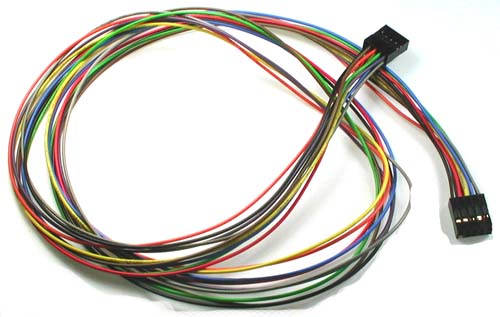 |
| The 8-way modular wiring hardness available for the U-HID was a real time saver. |
The U-HID has 7 header positions, for a total of 56 possible inputs/outputs, though you are limited to assigning a maximum of 50 connections by the U-HID software/firmware and by technical limitations of the board. There is also a Windows limitation of 32 gamepad buttons, so the remaining 18 switches have to be configured as keyboard buttons.
 |
| My switch wiring sketch. The yellow highlighted switches are better configured as gamepad buttons in software. |
Before wiring, I sketched out the proposed wiring path on a reversed image of the playfield. My strategy was to simply find 8 switches relatively close to each other and group them on the same 8-way harness. While I had to modify the actual wire paths to navigate obstacles that exist on the playfield, for the most part my final result resembles my sketch.
In case you missed an earlier post, the cabinet buttons will be handled by a separate U-HID, so I won't detail those here.
 |
| There are 16 switches on the top 3rd of the playfield, requiring 2 harnesses. |
Installation was straightforward. After mounting the U-HID in a central location, I simply connected a wiring harness and routed it along the desired path, using cable clamps to secure the wire harness to the board. I cut the black ground wire at the closest switch for that harness, and then at each switch location I cut a single wire to length, working from closest switch to furthest switch from the U-HID.
 |
| The 6 mid-playfield standup targets used another harness. I will coil and save the two spare wires for repairs if needed. |
Now this is where the Modern Firepower Pinball Project begins to distance itself from all other pinball machines, both factory and diy machines. Except for the black ground wire, I did not worry about the color of the wire going to each switch, nor the pin on the U-HID to which the switch would ultimately connect. In my solution, it simply doesn't matter! Any switch to any wire to any pin on the U-HID! The switches will be easily mapped later in software. You'll be amazed when you see how the software graphically guides you through the mapping process, which only takes a few minutes.
 |
| There are 3 harnesses running to the bottom half of the playfield to support the 24 switches that reside there. |
Had the wiring harness been available in all white signal wires, I would have used it to help illustrate how carefree it is to wire up a playfield using this solution. Compared to a normal pinball machine which was designed to have a specific pin connect to a specific switch using a specific colored wire, this approach of free-form wiring is a breeze!
Modern Firepower continues to earn its name.
 |
| All switch connections were soldered. |
After all 8 switch wires were cut, the 2nd unused connector had 8 wires of various lengths, making it possible to use it on the next set of switches. While I have 6 headers plugged into the U-HID, I only had to use 3 wiring harnesses, eliminating waste.
 |
| The black ground wire was simply daisy chained from switch to switch, minimizing total wiring. |
If you look closely (you can always click on the images to enlarge), you can see a common black wire that is daisy chained to the switches; this is the shared ground. By daisy chaining the ground connection, I further minimized total wiring on the playfield. Though I've never had the opportunity to study a real pinball playfield, I think a common power or ground connection is a standard wiring method, so nothing too notable here.
In total, Modern Firepower will have 46 separate switch connections to the U-HID, leaving only 4 spare switch inputs. At first glance, this could trick you into thinking that a single U-HID is not capable of supporting more complicated playfields, but that's not true. Outside of the dual kicker switches that trigger the slingshots, which I wired together into a single switch input, I wired every switch individually. While most switches need to be individual to trigger specific solenoids, lights, or accomplishments, there are many generic switches that don't have to be wired individually.
A good opportunity to reduce the total switch count are the 8 standup leaf switches that are scattered throughout the playfield, hiding behind rubber rings. These switches all have the exact same score and function in Firepower, and could be wired together as one switch. This would have free up 7 switch inputs, for a total of 11 spare connections. So a single U-HID could handle a playfield roughly 25% more complicated than the Firepower layout.
And if you needed more complexity, you can always use another U-HID, either a full-scale 50 input U-HID or an even smaller 8 input U-HID Nano.. You can utilize up to 8 U-HID devices on a single computer, so any playfield design is within reach.
Getting back to the playfield, I soldered every switch connection. Soldering wire connections is very important on a pinball machine, as the vibrations produced by the solenoids could shake loose any crimp on wire connectors.
Also, pinball switches typically have diodes on them to protect the circuit boards. The U-HID does not need these. If the switch I purchased already had the diode installed, I left it in place and connected the ground to the anode side of the diode, and the signal wire to the cathode side (indicated by the bar on the diode). If I wanted to, I could have cut diodes off completely, but I was too lazy. If the switch I purchased did not include a diode pre-installed, I simply skipped it and wired up the switch however I liked.
 |
| Reminds me of power lines running to all the buildings on the block. |
To test the switches I connected the U-HID to the PC via a USB cable, and I opened both Windows Notepad and the Windows gamepad calibration tool. I pressed each switch in turn, and for inputs configured as gamepad buttons an indicator light would indicate successful wiring. If the switch didn't act as a button, I switched over to the Notepad window and tried the switch again, which would result in a keyboard letter showing up, just like typing on a keyboard. If a switch didn't work in either the gamepad calibration tool or Notepad, that would have indicated bad wiring. Luckily every switch worked for me on the first wiring attempt.
Using both the gamepad calibration tool and notepad was a little bit of a pain, mainly because only the currently selected app would process any inputs. I realize now that if I had configured all inputs as keyboard characters, testing would have been much quicker, as I could have just used notepad (the 32 gamepad button limit in Windows prevents you from configuring all switches as gamepad buttons). I plan to add a switch monitoring utility to my pinball software in the future, which would make testing even easier, but that's not a critical feature at this time so it will have to wait.
At this point, the only switches that remain to be wired up are the top eject hole (which will have to wait until the playfield is removed from the rotisserie) and the 7 opto switches on the ball trough. The opto switches are special, as they have their own circuit board, and the signal they provide is incompatible with the U-HID.
The U-HID sends out a +5V signal on each connection, and a switch is pressed when the signal wire is connected to ground.
The ball trough opto board is powered by a +12V power source, and outputs a 0V signal when the ball position is open, and a +5V signal when a ball is in that trough position. Connecting the U-HID directly to the opto board could kill one or both circuit boards, and even if it didn't the signals are incompatible. I have to create an interface circuit board to integrate the U-HID and opto boards together. Basically, I have to use the +5V signals from the opto board to open a ground connection for each U-HID connection. I have picked a 7-way transistor to do the job, but haven't yet designed or tested the circuit. I'll make a separate post detailing this custom opto switch interface circuit after it is done.
Once I'm done with the opto switch interface board, I'll start wiring the lights.
Getting really close now!
Hey, I'm wondering what switch number is the "start" button? Thanks.
ReplyDeleteThere's no Start button on the playfield itself. The Start button is in the cabinet, on a separate controller.
Delete